SmartiPi Touch 2 setup - Pi 3 or 4
Raspberry Pi Bullseye issues
Pi OS Bullseye was released in November 2021. There are a number of issues rotating the camera in Bullseye. Raspistill and raspivid rotation are not supported. If you are having issues rotating the camera, please try Pi OS Buster. It is available in the Raspberry Pi imager under Raspberry Pi OS (other). Buster will be supported until 2024.
Documentation for the camera using Buster is available here.
Power supply
Always use a UL or CE marked wall power supply with the included splitter cables. Use a wall power supply that can deliver enough current for your application. For best results, use a 5.1 volt power supply to avoid low voltage warning on the display. The official Raspberry Pi power supply is recommended.
The splitter cables are only for use with the Raspberry Pi and Official Raspberry Pi display.

Step 1
Route the long end of the white cable under the display board. Attach the long end to the camera as shown. Install the display board onto the display with the supplied gold m3 screws. The standoffs that came with the display can be used to attach HAT boards to the Raspberry Pi. Attach the short white cable to the display board. Make sure the writing on the cable and blue tab is facing up like the photo.

Step 2
Mount the display into the case as shown and feed the camera and white cables as shown.

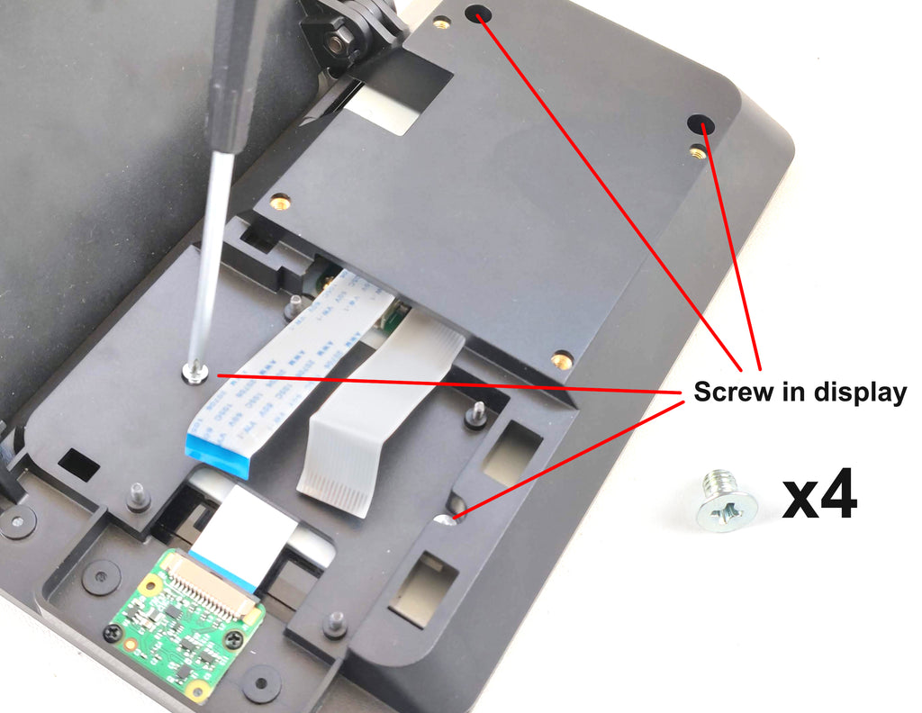
Step 3
Screw in the display using the four silver countersink screws.
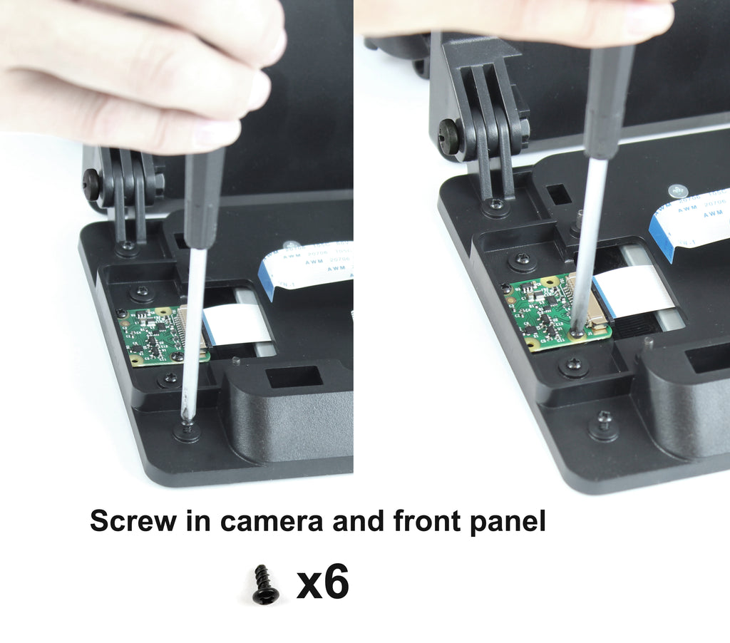
Step 4
Attach camera and front panel with six black screws. Please bear in mind the building block front panel will not work with V3 camera.
Step 5

Step 6
Assemble the fan onto the fan door. For best results the label should be facing toward the Raspberry Pi.

Step 7
Connect the wire to the GPIO pins. We suggest starting with low speed as it is quieter. If you get the temperature icon in the display, you can always move up to the high speed.

Step 8
Assemble the door. Be careful not to pinch the white cables.

Step 9
Assemble the housing onto the base. Important - Hold base on table while adjusting the display angle, then tighten the screws.


Securing the Raspberry Pi without the door
The standoffs that came with the display can be used to secure the Raspberry Pi. This would be an alternative to using one of the back doors.

Video conferencing with the SmartiPi Touch 2
To rotate the camera for browser based video conferencing follow the below steps.
In a command line enter
sudo nano /etc/rc.localThen go down and enter the following code above exit 0
v4l2-ctl --set-ctrl=rotate=90
Then enter CTRL+O to write out the file and then CTRL-X to exit.
Once rebooted that should have the camera rotated the correct way for most browser video conferencing sites.
HAT boards
HAT boards can be attached with the standoffs that came with the display. Use the m2.5 nuts that came with the SmartiPi Touch to fasten the HAT board down.

Back cover accessory
The back cover accessory (sold separately) attaches to the brass 75mm VESA mount inserts on the back. It is plain open box that you need to customize yourself.

Standard door GPIO
If you are using the standard door, the knockout can be cut with a knife to access the GPIO

VESA mount
The four VESA mounts inserts on the back are 75mm apart. You can use them to attach to aftermarket VESA mount adapters.

Product dimensions


