SmartiPi Touch 2 setup - Pi 3,4 or 5
Using this case with Raspberry Pi 5
In April 2024 a new gold colored Raspberry Pi 5 display ribbon cable was added to this kit. This display cable makes it compatible with Raspberry Pi 5. When using this case with Pi 5 there will be a warning in Pi OS that says.
This power supply is not capable of supplying 5A Power to peripherals will be restricted
There are no communication lines in our splitter cable therefore the Raspberry Pi will not be able to detect a 5A power supply even if it is connected. Therefore it is not possible to prevent this message from appearing.
You can override the restricting of the current to the USB ports by doing one of the two things below.
1 - Adding usb_max_current_enable=1 in /boot/firmware/config.txt
OR
2 - Enabling USB max current on the Pi OS desktop GUI under preferences -> configuration
Once enabled the Pi5 will not restrict power to the peripherals and will allow 1600mA to the USB ports. One thing to note is that even if you are using a 5A power supply, our splitter cable is only rated for 3A. If you try to draw more than 3A through our splitter, the voltage will drop too low for the Raspberry Pi to function and it will reboot.
Power supply
Always use a UL or CE marked wall power supply with the included splitter cables. Use a wall power supply that can deliver enough current for your application. For best results, use a 5.1 volt power supply to avoid low voltage warning on the display.
The 27W Raspberry Pi Power supply will work with our case but will only supply 3A. That is enough for most applications.
The splitter cables are only for use with the Raspberry Pi and Official Raspberry Pi display.

Step 1 (Raspberry Pi 3 and 4)
If using a Raspberry Pi camera, route the long end of the white cable under the display board. Attach the long end to the camera as shown. Remove the standoff that were holding the display board onto the display and replace with the supplied gold m3 screws. The standoffs that came with the display can be used to attach HAT boards to the Raspberry Pi. Attach the short white cable to the display board. Make sure the writing on the cable and blue tab is facing up like the photo.

Step 1 (Raspberry Pi 5)
If using a Raspberry Pi camera, route a 500 mm long Raspberry Pi 5 to Raspberry Pi camera cable under the display control board as shown. The 500mm long camera cable is not included with this case. Attach a Raspberry Pi camera to the end. Route the supplied gold display cable to the DSI connector on the display control board as shown. Install the display board onto the display with the four supplied gold screws. The standoffs that came with the display can be used to attach HAT boards to the Raspberry Pi later.

Step 2 (Raspberry Pi 3 and 4)
Mount the display into the case as shown and feed the camera and white cables as shown. The camera and camera cables are optional.

Step 2 (Raspberry Pi 5)
Screw the camera to the case as shown below with two of the small black screws. Route the camera and display cables through the case as shown below. The camera and camera cables are optional.

Step 3 (Raspberry Pi 3 and 4)
Screw in the display using the four silver countersink screws. Screw in the camera with two of the small black screws.
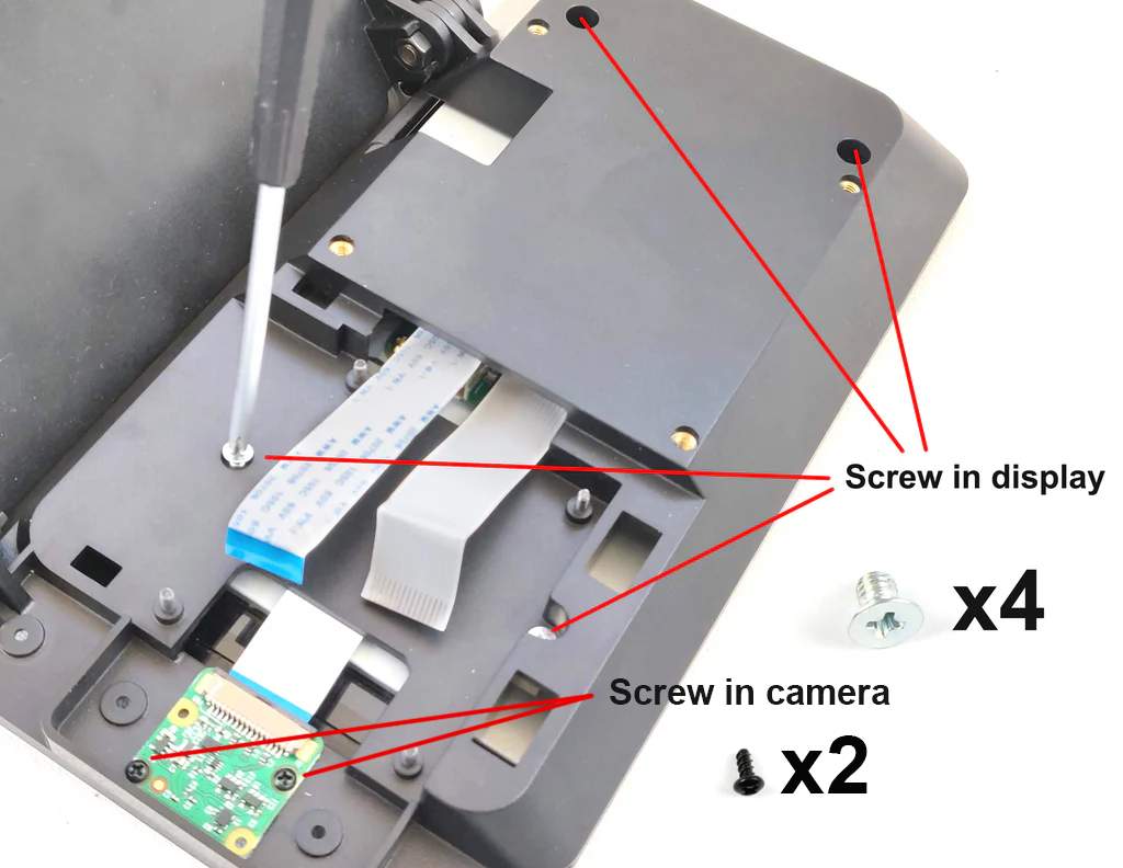
Step 3 (Raspberry Pi 5)
Screw in the display using the four silver countersink screws.

Step 4
Attach one of the front panels with four black screws. Please bear in mind the building block front panel will not work with V3 camera.

Step 5 (Raspberry Pi 3 and 4)

Step 5 (Raspberry Pi 5)

Step 6
Assemble the fan onto the fan door. For best results the label should be facing toward the Raspberry Pi.

Step 7
Connect the fan wire to the GPIO pins. We suggest starting with low speed as it is quieter. If you get the temperature icon in the display, you can always move up to the higher speed for more cooling.

Step 8
Assemble the door. Be careful not to pinch the white cables.

Step 9
Assemble the housing onto the base. Important - Hold base on table while adjusting the display angle, then tighten the screws.


Securing the Raspberry Pi without the door
The standoffs that came with the display can be used to secure the Raspberry Pi. This would be an alternative to using one of the back doors.

Video conferencing with the SmartiPi Touch 2
To rotate the camera for browser based video conferencing follow the below steps.
In a command line enter
sudo nano /etc/rc.localThen go down and enter the following code above exit 0
v4l2-ctl --set-ctrl=rotate=90
Then enter CTRL+O to write out the file and then CTRL-X to exit.
Once rebooted that should have the camera rotated the correct way for most browser video conferencing sites.
HAT boards
HAT boards can be attached with the standoffs that came with the display. Use the m2.5 nuts that came with the SmartiPi Touch to fasten the HAT board down.

Back cover accessory
The back cover accessory (sold separately) attaches to the brass 75mm VESA mount inserts on the back. It is plain open box that you need to customize yourself.

Standard door GPIO
If you are using the standard door, the knockout can be cut with a knife to access the GPIO

VESA mount
The four VESA mounts inserts on the back are 75mm apart. You can use them to attach to aftermarket VESA mount adapters.

Product dimensions


